Information
A PDF version can be downloaded here:
OpenLab User Guide for Coiled Tubing Drilling
Revised version: April 2026
Platform: OpenLab web-enabled drilling simulator
Simulator type: Coiled tubing drilling
A PDF version can be downloaded here:
About this guide
This guide explains how to create, edit and run coiled tubing drilling simulations in OpenLab. It is written for users who work through the web interface, but it also includes a short section on MATLAB and Python access through the OpenLab web API.
The guide is based on the OpenLab Coiled Tubing Drilling user guide source documents and has been rewritten for clearer language, more consistent terminology and easier publication in Ghost.
Introduction
OpenLab Drilling is a web-enabled simulator environment that makes NORCE computer models available through a browser-based user interface. The coiled tubing drilling simulator combines well-flow modelling with drill-string and coiled-tubing mechanics. The goal is to let users configure a realistic well, drilling assembly, fluids, geology and rig system, then run dynamic simulations and inspect the results through live graphs.
Coiled tubing drilling differs from conventional rotary drilling because the tubing is a continuous pipe stored on a reel and injected into the well. In OpenLab, this requires dedicated inputs for the coiled tubing string, bottom-hole assembly (BHA), injector and reel system, while still using familiar drilling concepts such as pump rate, rate of penetration (ROP), weight on bit (WOB), wellpath, geopressures, temperature and cuttings transport.
The simulator is intended for training, research, planning support and technology demonstration. It does not replace engineering judgement, operational procedures or formal well-control requirements.
Account and login
The OpenLab Coiled Tubing Drilling Simulator is accessed through the OpenLab web environment at live.openlab.app. Users normally sign in using an approved OpenLab account. Depending on the deployment, sign-in may be available through Google, Microsoft or an OpenLab user account.
To create or request an account:
1. Go to https://live.openlab.app/.
2. Select the preferred sign-in method or request a trial account.
3. Contact OpenLab if additional access, longer simulation time, API access or control-room functionality is required.
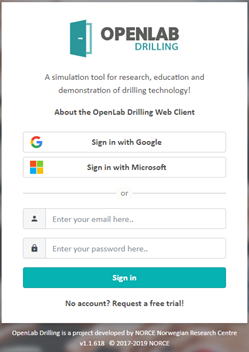
Login page for OpenLab.
Home Page
After login, OpenLab opens the Home Page. This page gives access to configurations and simulations. Configurations describe the physical and operational setup, while simulations are dynamic runs based on a specific configuration version.
From the Home Page, you can:
• create new configurations;
• open existing configurations;
• organize configurations in folders;
• access existing simulations;
• open user settings and account-related information.
The OpenLab icon in the upper-left corner returns you to the Home Page.
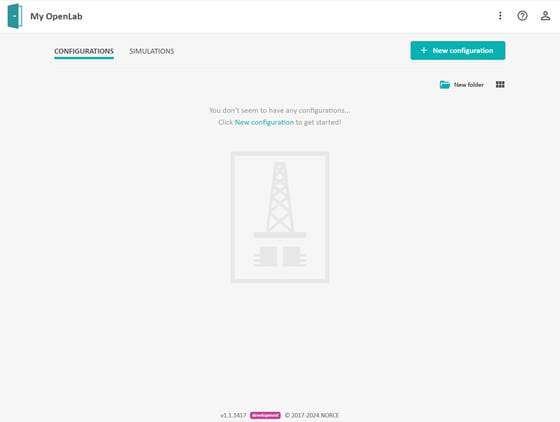
Home Page with configuration and simulation tabs.
For the best experience, use Google Chrome. OpenLab also runs in Microsoft Edge, Firefox and Safari, but some components may behave differently depending on browser version and screen size. The interface can be used on smaller screens, including mobile devices, but some functionality may be hidden or simplified.
Configurations
A simulation can only be created after a valid configuration exists. A configuration contains the input data required by the simulator, including the well architecture, wellpath, fluids, coiled tubing assembly, geology, rig equipment and scenario options.
OpenLab uses templates to simplify the setup process. A template gives a starting point that can be copied and modified. Validation rules check the input values and warn the user when the configuration is incomplete, inconsistent or outside accepted ranges.
Create a configuration
To create a new coiled tubing drilling configuration:
1. Go to the Home Page.
2. Click New configuration.
3. Select the drilling configuration type.
4. Enter a configuration name.
5. Select Offshore or Onshore.
6. Select a coiled tubing template.
7. Optionally place the configuration in an existing or new folder.
8. Click Create new configuration.
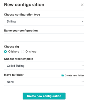
New configuration dialog for coiled tubing drilling.
The new configuration appears on the Home Page or inside the selected folder.
Configuration actions
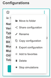
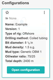
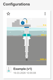
Each configuration is shown as a card. Hovering over a card displays key information about the configuration, such as name, version and selected setup. The three-dot menu opens quick actions.
Typical configuration actions include:
• move to folder;
• share configuration;
• rename;
• copy configuration;
• export configuration;
• add to favorites;
• delete;
• stop simulation, when relevant.
A star icon can be used to mark important configurations as favorites.
Edit a configuration
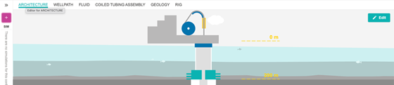
Open a configuration to review or edit the setup. The main configuration categories are shown as tabs. A category can be edited by clicking the Edit button in the upper-right part of the relevant panel.

When a parameter is changed, OpenLab checks whether the configuration remains valid. If an input is missing, inconsistent or outside an accepted range, Jill-Bit displays a validation message and identifies the affected parameters. In some cases the Reset all button can be used to revert invalid edits.
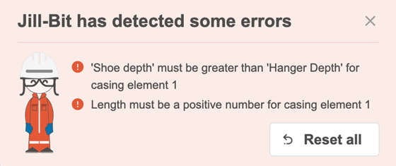
Jill-Bit validation message showing configuration errors.
Configuration categories
The coiled tubing drilling configuration is divided into six main categories:
1. Architecture
2. Wellpath
3. Fluid
4. Coiled Tubing Assembly
5. Geology
6. Rig
Each category represents part of the physical or operational system used by the simulator.
Architecture
The Architecture editor defines the physical layout of the well and flow system. It includes the riser and flow lines, casing and liners, and the open-hole section. The editor contains geometric inputs such as lengths, depths and diameters.
Typical inputs include:
• BOP position;
• riser and flow-line sections;
• choke, kill and riser booster lines, when included;
• casing and liner hanger depths;
• shoe depths;
• outer and inner diameters;
• open-hole length and diameter.
The Architecture editor validates the setup automatically. For example, casing shoe depth must be deeper than hanger depth, and lengths and diameters must remain physically meaningful. Import from CSV is not normally used in this editor; values are edited directly in the interface.
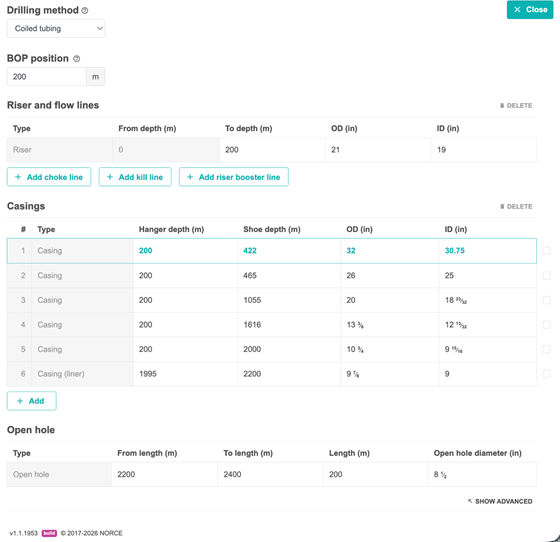
Architecture editor for riser, flow lines, casing and open hole.
Wellpath
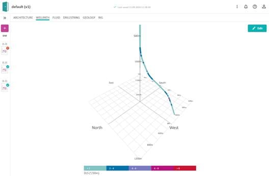
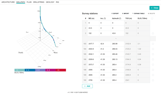
The Wellpath editor defines the trajectory of the well. The front page shows a 3D trajectory view, and the colors along the trajectory indicate dogleg severity (DLS). Click Edit to modify the survey data.
Wellpath data can be:
• entered manually;
• imported from a CSV file;
• exported to a CSV file for reuse or external editing.
The survey points normally include measured depth (MD), inclination, azimuth and calculated trajectory properties. The wellpath must be consistent with the architecture and the total well depth used in the simulation. Excessive dogleg severity may trigger validation warnings or restrict the setup.
Fluid
The Fluid editor defines the main and reserve drilling fluids. Both fluids are based on templates. The density entered in the Fluid editor is the default value used at the start of the simulation, but mud density can also be changed while the simulation is running if the relevant controls are available.
Fluid properties are edited manually. Import and export from CSV is not normally used in this editor.
Available fluid templates may include:
• Generic OBM 1;
• Generic OBM 2;
• Generic OBM 3;
• Generic OBM 4;
• Generic WBM;
• micronized barite;
• water.
The selected fluid affects hydraulic pressure loss, equivalent circulating density, temperature-dependent properties and cuttings transport.
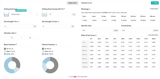
Fluid editor for main and reserve fluids.
Coiled Tubing Assembly
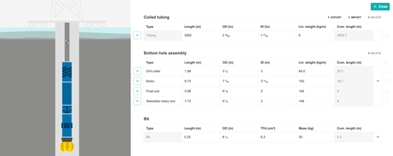
The Coiled Tubing Assembly editor defines the coiled tubing string and the BHA. Coiled tubing is a continuous pipe stored on a reel, straightened through the injector and pushed into the wellbore. In the simulator, the coiled tubing string is defined separately from the BHA.
The coiled tubing section normally includes values such as:
• string type;
• length;
• outer diameter (OD);
• inner diameter (ID);
• weight;
• elasticity or stiffness-related data, depending on the available template.
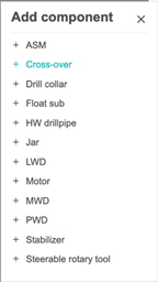
The BHA can be modified in a similar way to a conventional drilling assembly. Components can be added, removed or edited. Along-string measurement nodes can be added by selecting an ASM component from the add-component menu.
Geology
The Geology category contains three sub-editors:
• Geopressures;
• Geothermal;
• Formation.
These inputs describe the formation environment along the wellbore and are used by pressure, temperature, influx/loss, drilling mechanics and cuttings models.
Geopressures
The Geopressures editor defines pore pressure and fracture pressure profiles. Profiles can be listed either as functions of true vertical depth (TVD) or measured depth (MD), depending on the setup.
The profiles can be edited manually or imported from a CSV file. When a simulation is created, the geopressure curves can be used as limits for kick and loss calculations. If this option is enabled, influx may occur when open-hole pressure falls below pore pressure, and losses may occur when pressure exceeds fracture pressure, subject to the selected scenario settings.
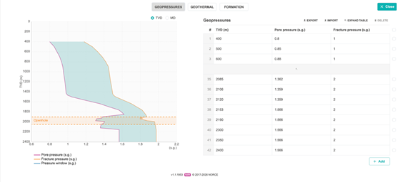
Geopressure editor with pore and fracture pressure profiles.
Geothermal
The Geothermal editor defines temperature as a function of depth. The temperature profile is used in dynamic temperature calculations and affects fluid density, rheology and other temperature-dependent properties.
The geothermal profile can be edited manually or imported from a CSV file. The editor also includes thermal properties for:
• air;
• water;
• solid material;
• alternative initial annulus temperature profile;
• alternative initial string temperature profile.
By default, the initial temperature in the string and annulus follows the geothermal temperature. If an alternative initial temperature profile is specified for only part of the well, OpenLab extrapolates it toward the geothermal profile for the remaining depth interval.
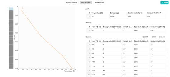
Geothermal editor with temperature profile and thermal properties.
Formation
The Formation editor defines rock and formation properties used by the drilling models. Formation strength is represented by unconfined compressive strength (UCS) as a function of depth. UCS is used when calculating WOB requirements for a given ROP. If no UCS values are entered, the simulation may use a default value.
The Formation editor may also contain:
• formation permeability;
• formation porosity;
• formation fluid composition;
• gas-water ratio or related fluid-composition parameters.
These values are especially important when influx, losses or formation interaction scenarios are enabled.
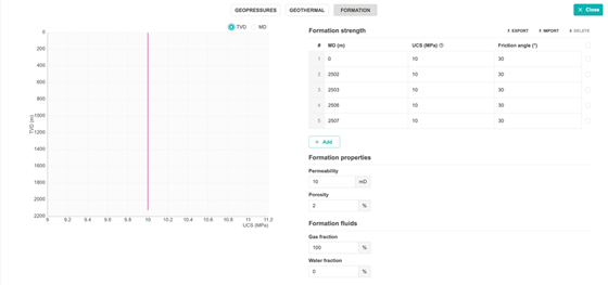
Formation editor with UCS and formation properties.
Rig
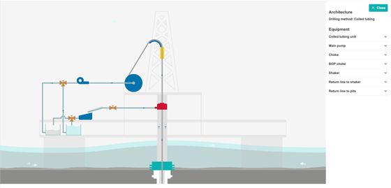
The Rig editor defines the equipment that affects flow, pressure response and string dynamics. The rig view highlights editable components when the user hovers over them. Components can be selected directly from the figure or opened through the Edit button.
The equipment setup is normally predefined in the selected template. Changing equipment parameters can significantly affect the simulation response, including flow distribution, pressure losses, hookload, torque, tubing movement and control behavior.
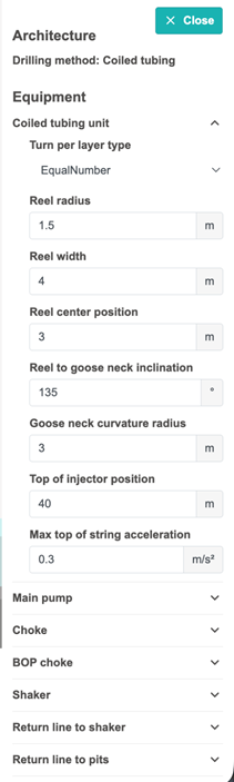
For coiled tubing drilling, the coiled tubing unit includes additional settings. The reel and injector setup can be configured in detail, including the turn per layer type. Available choices include:
• Equal Number;
• Unequal Number Start with Max;
• Unequal Number Start with Min.
Versioning of configurations
If a configuration has already been used to create a simulation, later edits create a new configuration version. Earlier versions remain stored together with their associated simulations. This makes it possible to trace which configuration was used for a given simulation result.
Locked historical versions can be opened and used to create new simulations. To edit a locked version, create a copy first. The configuration sidebar shows version history and associated simulations.
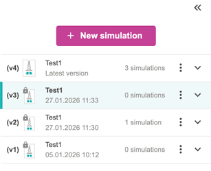
Configuration versioning sidebar.
Simulations
A simulation is a dynamic run based on a specific configuration version. Simulations can be started from the configuration view or from the simulations view. In the web interface, simulations can be controlled manually or through predefined setpoint sequences.
OpenLab simulations can also be accessed through the web API. This is described in the MATLAB and Python section.
Create a new simulation
To create a simulation:
1. Open the relevant configuration or go to the simulations view.
2. Click New simulation.
3. Enter a simulation name.
4. Review the available capacity, time limit and active simulation count.
5. Review or adjust Initial conditions.
6. Review or adjust Model configuration.
7. Review or adjust Drilling scenario settings.
8. Click Create new simulation.

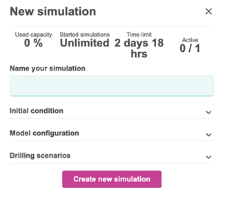
Initial conditions
The Initial conditions tab defines the starting state of the simulation. Depending on the selected template, inputs may include:
• initial bit depth;
• initial top of string position;
• main pit mud volume;
• reserve pit mud volume;
• main pit temperature;
• reserve pit temperature.
If values are not entered manually, OpenLab may suggest default values based on the configuration.
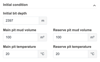
Initial conditions in the simulation dialog.
Model configuration
The Model configuration tab controls which physical models are enabled and how the simulator performs the calculations. Available options depend on the selected deployment and template, but may include:
• simulation step duration;
• transient or steady-state torque and drag;
• temperature model step size;
• transient torque and drag model;
• cuttings model;
• gel model;
• piston effect;
• low temperature model;
• selectable ROP models;
• restart behavior from saved simulation profiles.
Higher-fidelity models may improve physical detail but can increase simulation time. Choose the model level that matches the objective of the simulation.
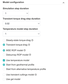
Model configuration settings.
Drilling scenario settings at initialization
The Drilling scenario tab controls whether influx, losses and pipe washout are included from the start of the simulation.
Typical options include:
• No influx and loss: no influx or losses are simulated, even if pressure crosses the geopressure limits.
• Based on geopressure: pore-pressure and fracture-pressure curves define the influx and loss limits. A kick-off time can be used to delay the start of influx/loss calculations.
• Direct influx/loss: the event is defined directly by kick-off time, depth, mass rate and total mass.
• Direct loss: loss is triggered directly according to the specified settings.
• Pipe washout: a washout can be initialized at a defined distance from the bit, below the BOP and above the bit.
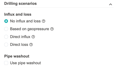
Drilling scenario settings during simulation creation.
After Create new simulation is selected, OpenLab initializes the model. When initialization is complete, the simulator begins calculating the dynamic state of the well based on the selected controls and setpoints.
Drilling parameters and control modes
While the simulation is running, the left-side control panel provides the main drilling parameters. The visible controls depend on the configuration and enabled equipment. For example, choke, kill and riser booster controls are shown only when the corresponding equipment is part of the architecture.
Common controls include:
• main pump flow rate;
• tubing velocity at injection;
• auto driller mode;
• ROP setpoint;
• WOB setpoint;
• PI-controller gains, such as Kp and Ti;
• pressure-control mode;
• choke opening;
• BOP open/close status.
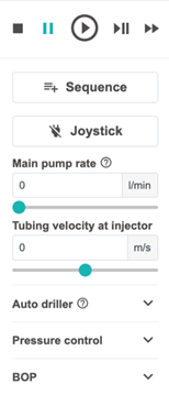
Drilling parameters panel during simulation.
Manual mode
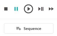
In Manual mode, setpoints can be changed while the simulation is running. The simulation playbar controls the calculation progress.
Common playbar actions include:
• Run: starts or resumes the simulation.
• Fast-forward: runs faster than real-time when performance allows it.
• Single step: advances the simulation by one calculation step.
• Pause: temporarily holds the simulation.
• Stop and complete: ends the simulation and gives the option to save or delete it.
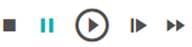
Manual simulation playbar.
If a simulation is paused for too long, or the user logs out, the system may automatically stop and complete the simulation. This prevents too many inactive simulations from consuming OpenLab resources.
After completion, the setpoint history can be exported through View setpoints. Manually changed setpoints are registered and can be reused in later simulations.
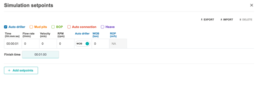
Sequence mode
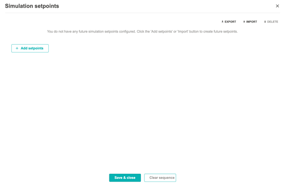
Sequence mode runs the simulation using a predefined set of setpoint changes. This is useful when a scenario must be repeated, documented or shared.
A sequence can be created by:
• using the table editor; or
• importing a CSV file.
For each setpoint, specify the time at which the change occurs and the values to apply. Only checked parameters are included in a given setpoint row. Sequences can be exported and imported for reuse across configurations.
Simulation graphs
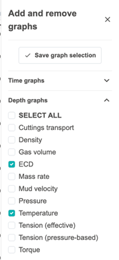
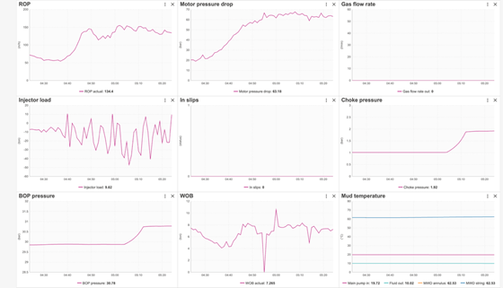
Simulation results are displayed live in the graph area. Graphs can be time-based, depth-based or state-based depending on the selected result. Use Add/remove graphs to choose which graphs are shown.
Typical graph groups include:
• BHA and string state;
• cuttings transport;
• density;
• downhole volume;
• ECD;
• mass rate;
• mud velocity;
• pressure;
• temperature;
• torque;
• torsion;
• hookload or related mechanical loads, depending on the active model.
Graphs can be arranged by drag-and-drop to create a custom dashboard. If graphs do not appear as expected, use the refresh button in the simulation window.
Other features
The simulation toolbar gives access to additional features. The exact icons may vary by deployment, but commonly include interface options, 3D view, graphs, notifications, help and user settings.

Simulation toolbar with feature icons.
More menu
The More menu contains utility functions that are useful during setup, review and sharing.
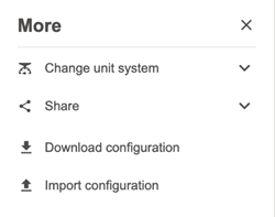
More menu with unit, share, download and import actions.
Change unit system
OpenLab can display values in different unit systems. The standard choices are:
• SI or base units;
• metric units;
• imperial (UK) units;
• US customary units.
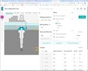
Unit system selection.
Share
The Share function can copy the current page link to the clipboard or open the default email client with a share link. Each configuration has a unique configuration ID, and each simulation has a unique simulation ID. These IDs can be seen in the browser URL.
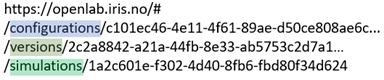
Configuration and simulation identifiers in the URL.
Download configuration
After a simulation or configuration has been created, the configuration can be downloaded as a .json file. This is useful for archiving, sharing or moving a setup between environments.
Import configuration
Before starting a simulation, a previously exported .json configuration can be imported. Always validate the imported setup before using it for new simulations.
Drilling scenarios
The drilling scenario menu allows selected events or model modifiers to be activated before or during a simulation. Available scenarios may depend on the selected model configuration and deployment.
Common scenarios include:
• pack-off or ledges;
• pipe washout;
• manual influx/loss;
• friction changes;
• plugged bit;
• heave.
Use scenarios carefully. Enabling or changing scenarios during a run can strongly affect the dynamic response and may stop the simulation if the resulting state is outside model limits.
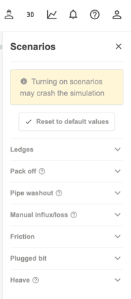
Drilling scenarios menu.
Pack-off or ledges
Bridging, ledges or pack-off behavior can be simulated when the relevant scenario is available. The parameter descriptions are available through information icons in the interface.
Pipe washout
Pipe washout must normally be enabled when the simulation is initialized. The washout location is defined relative to the bit and must be below the BOP and above the bit. During the simulation, the washout can be activated or deactivated, and the washout fraction can be set from 0 to 100%.
Manual influx/loss
Manual influx/loss requires the simulation to be initialized with the corresponding option enabled. The event can occur in casing or open hole. A positive mass rate represents influx, while a negative mass rate represents losses. The user specifies the location and total mass. Formation fluid composition is defined in the Geology - Formation editor.
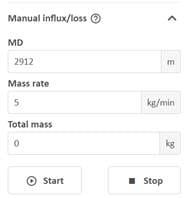
Manual influx and loss scenario panel.
Friction
Hydraulic friction in the annulus and drill string can be adjusted during the simulation. This directly affects pressure losses. Mechanical friction affects torque, hookload and related string mechanics. The available parameters depend on whether steady-state or transient torque and drag models are active.
Plugged bit
A plugged bit can be simulated by reducing the active bit-nozzle fraction. A value of 100% corresponds to no plugging. Lower values represent partial plugging and increase the restriction through the bit.
Heave
Heave is modelled through crown-block compensation. The user can configure amplitude, period and compensation level. Heave compensation is normally not applied during connections.
Error messages and Jill-Bit
When OpenLab detects an error in the configuration or simulation, the notification icon displays a warning. Jill-Bit explains what is wrong and where the relevant input can be corrected. Use these messages before starting or continuing a simulation, because a small input inconsistency can cause large changes in the model response.
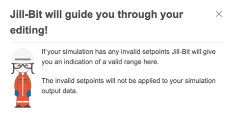
Error notification and Jill-Bit guidance.
Help and user menus
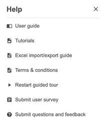
The Help menu contains shortcuts to guidance and support resources. Available items may include:
• User Guide;
• Tutorials;
• Excel import/export guide;
• Terms and conditions;
• Restart guide tour;
• Submit user survey;
• Submit questions and feedback.
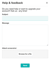
The User menu gives access to profile, license and settings information for the current user.
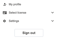
User menu.
MATLAB and Python interfaces
OpenLab simulations can also be accessed through the OpenLab web API. This allows external tools, such as MATLAB and Python, to create workflows around the simulator.
A typical API workflow is:
1. Create and validate the simulation configuration in OpenLab.
2. Export or obtain the required API key from OpenLab.
3. Use the MATLAB or Python template script from the OpenLab tutorials as a starting point.
4. Authenticate using the API key.
5. Start a simulation, update setpoints and retrieve results through the API.
The web interface remains the recommended starting point for building and validating the configuration before using external scripts.
Example: start a coiled tubing drilling simulation
The following example shows a basic sequence for starting drilling.
Before applying ROP
To start drilling, the bit must be on bottom and weight must be applied to the bit. If Bit depth is less than Total well depth, move the bit to bottom by adjusting Tubing velocity at injection. Positive velocity moves the tubing downward; negative velocity pulls it upward.
ROP and tubing velocity both control axial movement. When the bit is on bottom, the ROP setpoint overrides a positive tubing velocity. A negative tubing velocity pulls the string upward and disables the ROP control. The ROP setpoint is active only when the bit is on bottom.
Example simulation controls used when starting drilling.
Step-by-step start procedure
1. Move the bit to bottom. Set a positive tubing velocity at injection and run or fast-forward the simulation until bit depth equals total well depth.
2. Establish circulation. Set the main pump flow rate, for example 2000 l/min or 530 gpm, to transport cuttings.
3. Apply drilling control. Set an ROP, for example 20 m/h or 65 ft/h, to apply weight on bit and start drilling.
4. Monitor cuttings and pressure. Review graphs such as cuttings transport, cuttings bed, ECD, pressure and pump rate.
5. Adjust setpoints if needed. If cuttings accumulate, increase circulation, adjust drilling rate or review the selected cuttings transport model.
Practical checklist
Before running a coiled tubing drilling simulation, check the following:
• The correct drilling method and template have been selected.
• The architecture is physically consistent and validated.
• The wellpath reaches the planned total depth and has acceptable dogleg severity.
• The main and reserve fluids have realistic density and rheology.
• The coiled tubing string and BHA have the intended dimensions and components.
• Geopressure and geothermal profiles cover the required depth interval.
• Formation strength and permeability inputs are consistent with the planned scenario.
• Rig and coiled tubing unit parameters match the intended setup.
• Initial bit depth, tubing position and pit conditions are reasonable.
• The selected model configuration matches the purpose of the run.
• Influx/loss and washout options are enabled only when required.
• The graph layout includes the key variables needed to evaluate the run.
Glossary
ASM: Along-string measurement node or sensor component.
BHA: Bottom-hole assembly.
BOP: Blowout preventer.
DLS: Dogleg severity, a measure of wellpath curvature.
ECD: Equivalent circulating density.
Geopressure: Pressure profile describing pore pressure and fracture pressure.
MD: Measured depth along the wellbore.
OBM: Oil-based mud.
ROP: Rate of penetration.
TVD: True vertical depth.
UCS: Unconfined compressive strength.
WBM: Water-based mud.
WOB: Weight on bit.
Dan Sui Associate Professor at UiS
Department of Energy and Petroleum Engineering

Mats Hermansen
SVP Sales, Exebenus


