Information and Login
A PDF version can be downloaded here:
The Web-Enabled Drilling Simulator is accessible at live.openlab.app. To learn how to create an account, see the tutorial below.
Create an Account
To create an account, start by navigating to https://live.openlab.app/ where you should see a form similair to the one below.
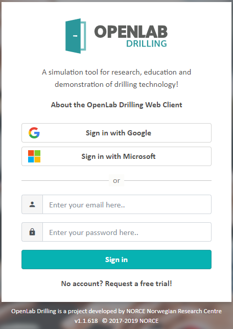
To create a free trial account, simply click one of the two social login buttons and you will be redirected to login to your respective Google or Microsoft account. Once authenticated by Google/Microsoft, your OpenLab account will automatically be created and associated with the account name you just logged in with. You will then be redirected back to OpenLab and ready to simulate the drilling process!
If at any time you would like to unlock the full features, extend your simulation limitations, or take a tour of our Control Room, contact us! Or for more info about our plans, check out https://openlab.app/pricing/.
If you have not signed up already, you may use a Google account or request an account using the contact form. You will then be given a limited trial user account.
After logging in, you will be directed to the Home page, which gives an overview of your configurations and simulations (if any). Here you can create, move, and delete configurations. In the top right corner, you will find your personal settings and other user-specific information. You can always go back to the Home page by clicking the OpenLab icon (the door) in the top left corner.
For the best experience, use a Google Chrome web browser. It will also run on Edge, Firefox, and Safari; however, some of the components might look strange or not work properly. You can use the Web Enabled Drilling Simulator at any screen size including a mobile device; some functionality is hidden for smaller mobile sizes
Configuration
The objective of the Web-Enabled Drilling Simulator is to run simulations. However, to create a simulation, you need to have a valid configuration in place. It is important to understand that each simulation is based on a distinct configuration.
A configuration consists of hundreds of input parameters that are used by the computer models to calculate the well flow and drillstring behavior. When you change one or several of the input parameters in the configuration, it will affect the results when running a simulation.
In OpenLab, we have tried to simplify the configuration process. The computer models behind OpenLab Drilling are extremely advanced, and the variety of input parameters are huge. It can be difficult for the user to know the exact value of each input parameter for all the elements and components. Therefore, you are given a set of template configurations to start with. To create your specific configuration, you can simply start from one of the existing templates and modify it. To avoid any unphysical configurations and to avoid any input parameters that are outside the acceptable range of the computer model, a set of validation rules need to be satisfied. When changing a configuration, you may therefore see an error message when the input parameters are invalid.
All the template configurations in OpenLab Drilling are based on a back-pressure Managed Pressure Drilling (MPD) setup. This does not mean that you need to use the MPD choke and back-pressure pump though. Simply leave the MPD choke open, and your configuration is similar to a conventional drilling operation with respect to circulation system and drillstring mechanics.
Create a Configuration
Before you can run a simulation, you must first create a well configuration. This video and accompanying tutorial teaches you how to create a configuration from one of several templates we have created.
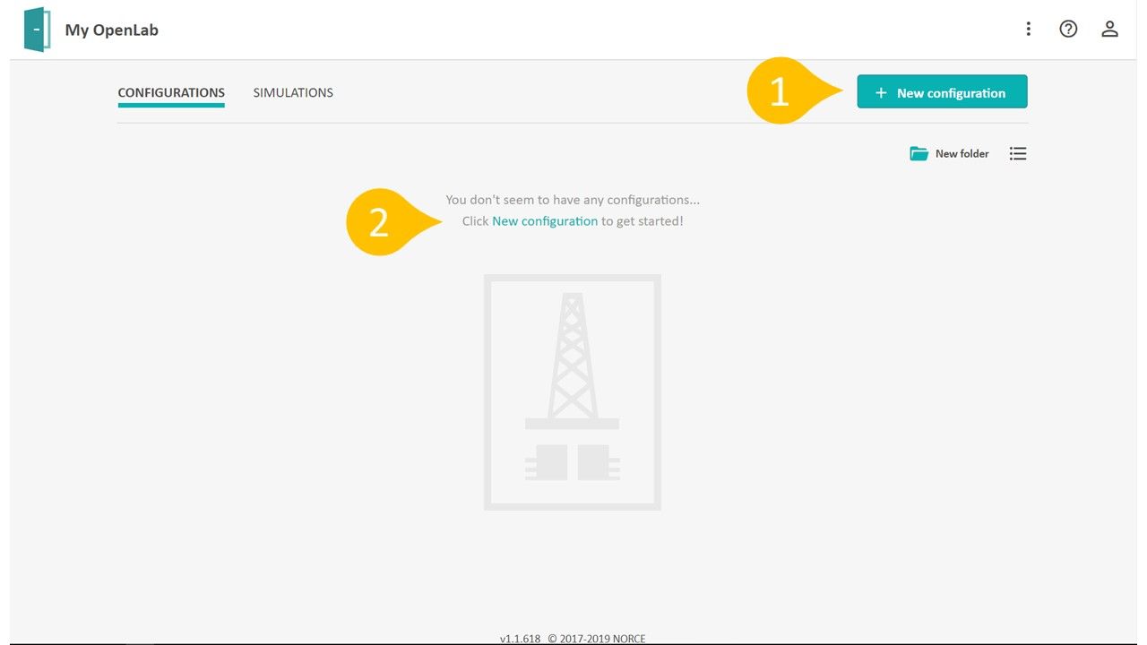
From the homepage, either click the new configuration button (1), or if you have no configurations yet, the New configuration text (2).
New Configuration Inputs
After pressing New configuration simply fill out the form in
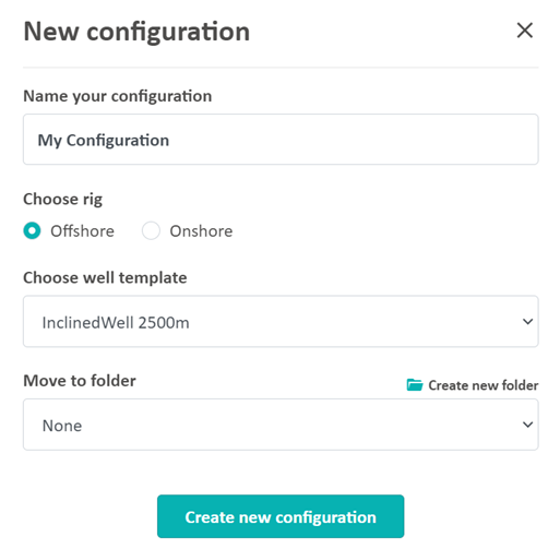
1) Name your configuration anything you want, as long as a configuration with that name does not already exist. We will call this simulation My Configuration
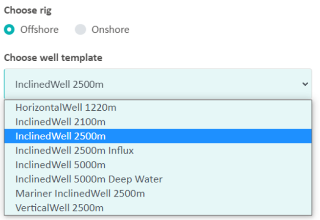
2) Select which type of rig best describes the well configuration you want to drill with. The main options are:
* Offshore
* Onshore
We will select Offshore
3) The new configuration is based on a selected template. These templates are examples of wells of different length and inclination. To make things easier to get started, we have created several templates to choose from as a starting guide. The 3 main templates are:
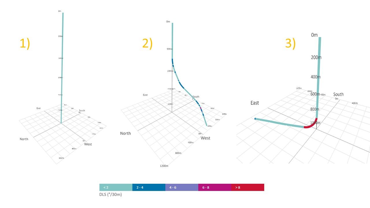
As you can see, these templates main differences are the well geometry, which plays a pivotal role in the drilling process.
From the Choose well template drop-down list, select the one you believe will best fit your planned well.
4) Finally, we select or make a folder to place this configuration in if you would like, e.g. Turtorials.
Your new configuration will then be visible on the Home page, or in one of your folders. It is also possible to mark some of your configurations as favorites. They will then appear at the top of the Home page under the Favorites heading.
Configuration Editing
To see how to edit a configuration, and some tips/tricks to using our configuration editors, see our main tutorials page, and select and filter by Configuration
Edit a Configuration
Editing an existing configuration can be done from any of the edit pages (editors) in your configuration:
A configuration item can be edited by clicking the “Edit” button:
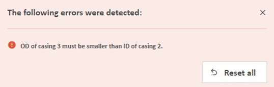
When editing a configuration, a set of validation rules will automatically be applied to secure that the configuration is still valid for the computer model to initialize and run. If one or several of the input parameters are outside the acceptable range, you will be given a warning along with a message. The message will guide you to the locations where the input parameters need to be corrected. If you want to go back to the last valid version, you can reload the page (press F5 on the keyboard or reload page on tablets), or click the “Reset all” button in the error message:
Be aware that if your configuration has already been used to create a simulation, any changes to the configuration will create a new version. Previous configurations along with corresponding simulations are stored and can be viewed in the Configuration sidebar, located as a pop-up menu on the left side of the edit pages.
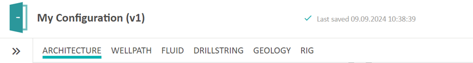
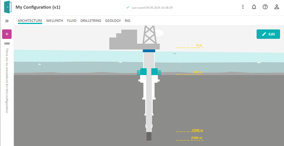
Architecture
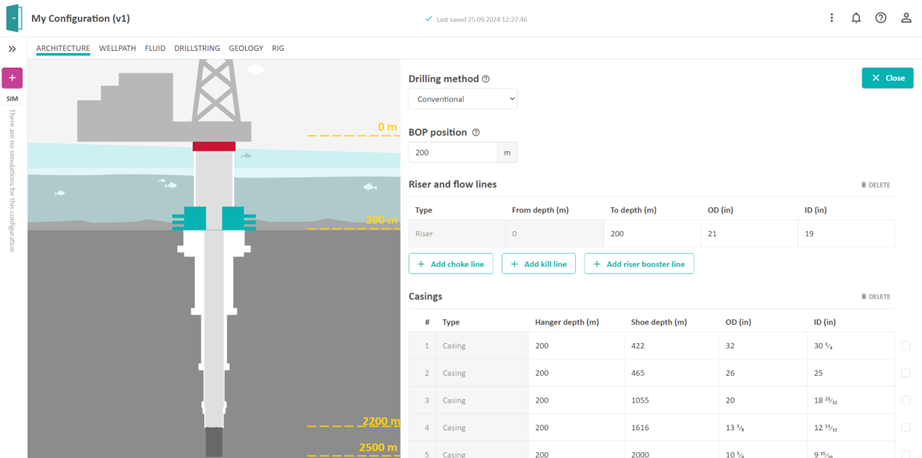
In the Architecture editor, you can select the drilling method and edit lengths and diameters of the riser, casings, liners and open hole section. Choke and kill lines can be added for all drilling methods except for external riser lift pump and reversed circulation. Riser booster line can be added for all drilling methods except for back pressure MPD and reversed circulation. Just click on any element on the figure, and you will see the table in which you can edit. It is not possible to import any data for this editor, so you must edit manually.
In this editor you can easily get validation errors. If you edit e.g. an inner diameter (ID) that does not allow any other casings to be run inside, you will be given a warning. You will be given warnings that are related to this editor, or it can be from other editors in the configuration that are affected. We hope that the error messages guide you to the right place for correcting errors in your configuration.
Drilling Method
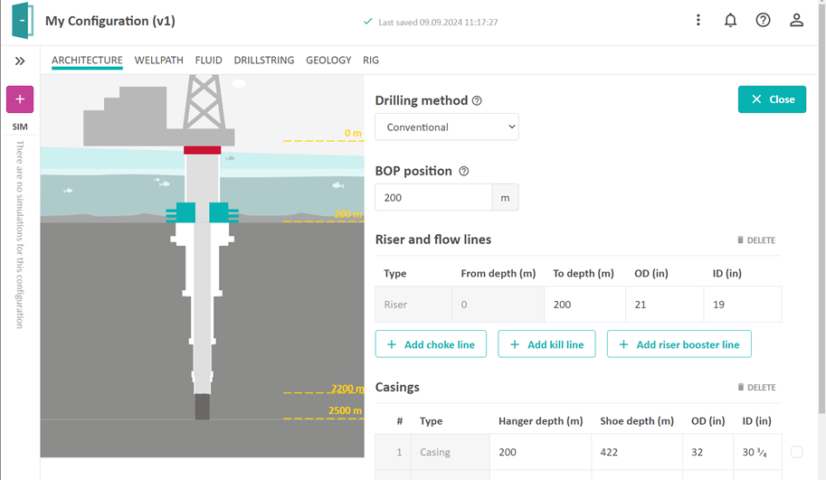
An important thing to select is the Drilling method in the Architecture page. The drilling method can be changed in the drop-down menu, and required pumps and chokes will be added or removed to the configuration. Note also that Kill and Choke lines can be added to any configuration to enable simulation of well control incidents.
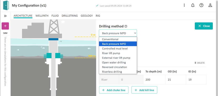
Conventional
A conventional drilling operation (also referred to as open-loop drilling) uses the drilling fluid hydrostatic pressure to balance between the pore and fracture pressure gradients without the assistance of an annular pressure control system.
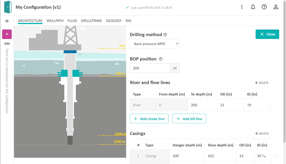
Back Pressure MPD
The MPD choke pressure on surface (back pressure) is used to control the bottom hole pressure by adjusting the MPD choke opening automatically. A back pressure pump can also be applied.
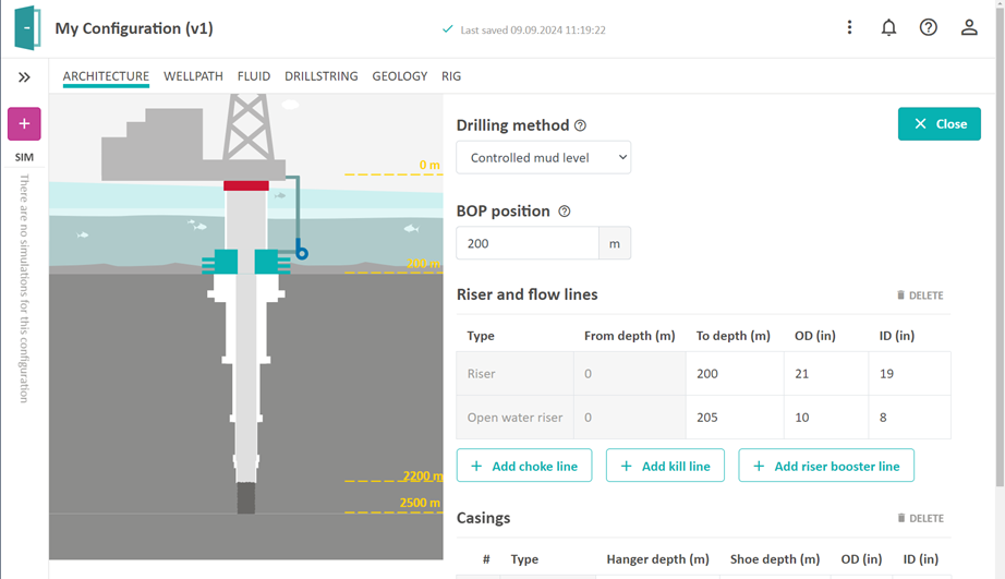
Controlled Mud Level
A lift pump is used to control the mud level inside the riser. The mud return goes via the lift pump through the open water riser (mud return line). The connection point between the open water riser and the annulus is determined by the number in the ‘To depth’ column for the open water riser.
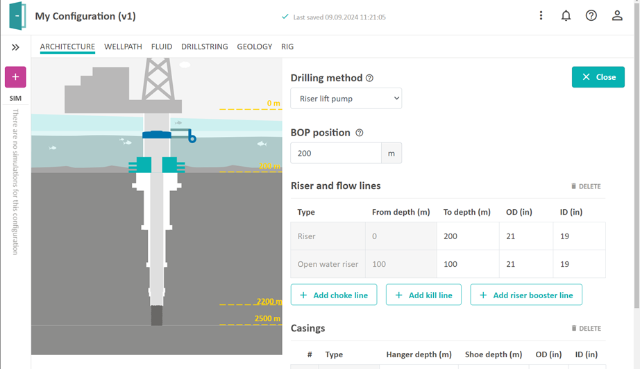
Riser Lift Pump
An RCD is placed somewhere in the riser, together with a lift pump which is clamped onto the riser and lifts the mud from below the RCD and back into the annulus above the RCD. The position of the riser lift pump is determined by the number in the ‘To depth’ column for the open water riser.
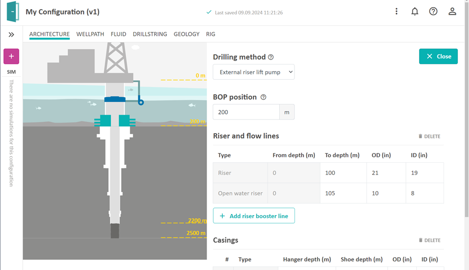
External Riser Lift Pump
The External riser lift pump configuration is like the Riser lift pump, except that the return flow is not pumped back into the annulus above the RCD, but instead goes through an open water riser to the surface. The position of the External riser lift pump is determined by the number in the ‘To depth’ column for the open water riser. To be able to simulate such a configuration we also need a casing (riser) element in the casing table which connects the riser to the casing(s).
Open Water Drilling
The Open water drilling configuration uses a lift pump and an open water riser for the return of mud to the surface. The connection point between the Open water riser and the annulus is determined by the number in the ‘To depth’ column for the open water riser.

For this configuration it is also possible to enable the use of an additional lift pump called mid-water lift pump by using a checkbox in the rig configuration page and selecting the position of the pump.
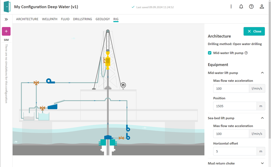
It is also possible to specify the horizontal offset which is the horizontal distance between the lift pump and the connection point between the annulus and the open water riser.
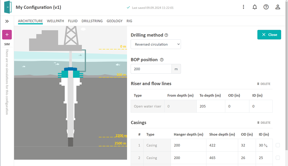
Reversed Circulation
The Reversed circulation configuration is like the open water drilling configuration except that there is no lift pump,. Since the purpose is to circulate in the opposite direction than the one used for conventional drilling, we require that the bit nozzle area (or total flow area) should be large and that there is no float valve in the drillstring. Be aware that narrow inner diameter of drillstring elements will result in large pressures in the annulus.
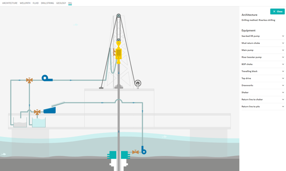
Riserless Drilling
The riserless drilling is like the open water configuration except that there is no RCD and no conventional riser.

Wellpath
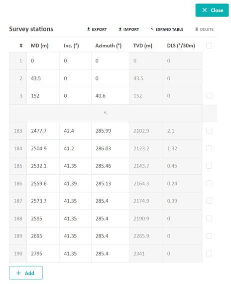
The front page of the Wellpath editor shows the trajectory of your well. The plot can be zoomed in/out with the mouse wheel scroll, rotated with left mouse click movements, and moved with right mouse click movements. The different colors on the trajectory refer to the dog leg severity (DLS). To edit the wellpath, push the Edit button:
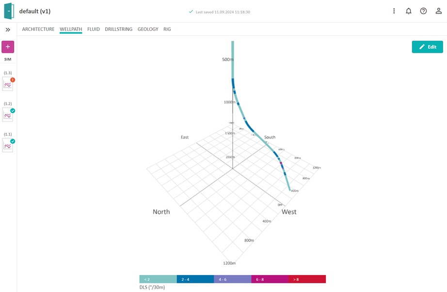
For the Wellpath editor you have the possibility to import the survey points from a CSV file (see Chapter 6). You can edit manually as well, but beware that there are limitations on the dog leg severity (you will get an error message if the DLS is too high). Usually there are many survey stations, so the table is collapsed by default. To see all the stations, click the expand arrow in the middle of the table.
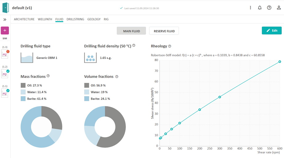
Fluid
In the Fluid editor, you can edit two fluids, Main Fluid and Reserve Fluid, by pressing the Edit button. Both fluids are based on templates which can be modified to your choice of mud. The density of the mud can also be changed during simulations, but the value you enter in the Fluid editor is your default value.
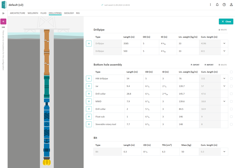
Drillstring
The drillstring, bottom hole assembly (BHA), and bit can be edited by clicking on each row. The BHA elements can be selected from a drop-down menu by clicking the + sign. Some elements in the BHA and drillstring also have some additional parameters that can be found by expanding the drop-down arrow in the lower right corner of its respective table row. This editor is also likely to give you validation messages when you start editing. Hopefully the messages will guide you to the right locations to change your configuration into a valid configuration.
If you want to add along string measurement nodes to the drill string, you can enter the + button and choose ASM among the components. On the simulation graphs you will then be able to read the simulated pressure value from this sensor.
Geology
The geology editor contains three sub editors: geopressures, geothermal and formation.
Geopressure
The geopressure profiles define the pore pressure and fracture pressure at any depth along the wellbore. You can list these profiles as functions of the True Vertical Depth (TVD) or as functions of the actual well-path Measured Depth (MD). To edit the geopressure profile, click the Edit button.
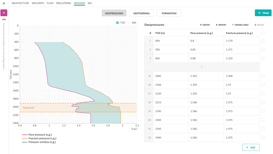
The profiles can be edited manually or by importing from a CSV file. Beware that when creating a new simulation, you can select if you want to use the geopressure profiles as limits for the kick and loss simulations.
Geothermal
The geothermal profile is given as temperature gradient as a function of depth. This profile is used in the dynamic temperature calculations and to model e.g. the rheology and density of the drilling fluid at any depth of the well. To edit the geothermal gradient values, click on the Edit button. The profiles can be edited manually or by importing from a CSV file.
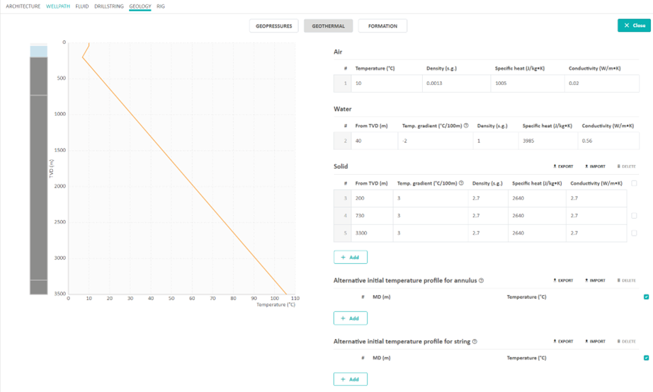
By default, the initial temperature in the string and annulus will be the geothermal temperature. It is also possible from this page to specify an alternative initial temperature profile for the string and annulus. This can be selected when starting a simulation. The alternative initial temperature profile will be extrapolated towards geothermal if it is not specified for the entire well.
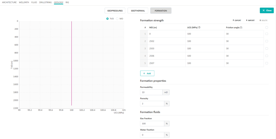
Formation
The formation strength is used in calculation of weight on bit (WOB) for a given rate of penetration (ROP). Formation strength is given by the unconfined compressive strength (UCS) as a function of depth. If no UCS values are entered, a default value of 100 is chosen in the simulation. Formation permeability, formation porosity, and formation fluid composition (gas – water ratio) is also specified in this editor.
Rig
The Rig editor is where you can change input parameters for the different equipment that are affecting the fluid flow and drill string dynamics. When you hover over the figure, you can see which components are editable. Click on one of them (or click the Edit button) to open the input table to make any changes.
Versioning
Earlier versions of a configuration are stored and locked, but can be used to generate new simulations. When a version is locked, it means that it has simulations associated to it, and therefore needs to be kept for reference. To keep track of the history of your configuration and the associated simulations, please navigate to the sidebar in your configuration view. You may need to expand this sidebar by pressing the expand button in order to see the versions. In the sidebar, you can view earlier versions and create new simulations on them. However, if you want to edit an old (locked) version, you are asked to create a copy before you can edit. Locked configurations are indicated with a blue background color and a text field.
Simulation
A simulation in OpenLab can only be done after a configuration has been made. Every simulation is based on a distinct configuration. A simulation can be run from a web browser or from any other interface that can connect to the OpenLab web API. This section is about simulations in the web browser. Later in this document, we will guide you through how to set up simulations from Matlab and Python.
Interactive
Create a Simulation and Drill
This tutorial teaches you how to run a simulation interactively and what must be done in order to drill.
Create a New Simulation
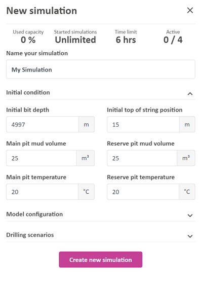
A new simulation can be created from the configuration view or from the simulations view by pushing the “New Simulation” button.
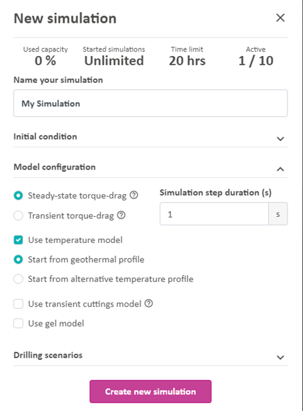
When creating a new simulation, you need to specify the name of your simulation and/or any advanced settings you would like. In the “Initial conditions” tab you can set initial bit, initial top of string position, and initial pit condition.
In the “Model configuration” tab, various models can be turned on or off. You can choose between a steady-state and transient torque and drag model. The steady state torque and drag model is a simplified torque and drag model. Simulation step duration can be set to between 0.1 and 1 second. Note that decreasing the step duration will decrease the simulation speed. The transient torque and drag model is an advanced torque and drag model. The step duration is 0.1 second, however the actual step in the torque and drag model is 10 ms. Note that it takes a longer time to simulate with this model than the steady state torque and drag model. For the transient torque and drag model you can choose between the MSE and Detournay ROP model.
It is also possible to turn off the temperature mode. By default, the temperature model in the drillstring and annulus is equal to the geothermal temperature, but it is also possible to start from a predefined temperature profile specified in the configuration page. In addition, a transient cuttings model and a gel model can be turned on.
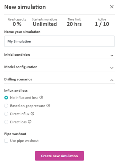
In the “Drilling scenarios” tab, you can select whether you want to be able to simulate influx/losses or not. Influx and losses are by default turned off. No influx and losses will then occur in the simulation even if the pressure in the open hole section is below the pore pressure or above the fracture pressure. If you choose “Based on geopressure”, the geopressure curves will define your boundaries for influx and losses, but no Influx or loss will occur before the kick-off time, which will give the user a chance to start circulation or in other ways preparing the simulation of the influx or loss. Influx will occur if the pressure in the open hole section is below the pore pressure and losses will occur if the pressure in the open hole section is above the fracture pressure. The intensity of the influx or loss is a function of the formation properties such as permeability and porosity that can be edited in the Geology configuration editor.
Direct influx/loss will override the geopressure settings. At the kick-off time, an influx/loss will occur at the specified depth (MD) with the specified mass rate. The influx/loss will stop when the accumulated influx/loss reaches the specified total mass. The direct influx/loss cannot occur in the riser.
To simulate pipe washout, the “Use pipe washout” checkbox must be selected when initializing the simulation. The location of the washout is determined by a distance from the bit. The washout must be located below the bop and above the bit.
Click the “Create new simulation” button to create a simulation. When creating a simulation, the computer model is first initialized and then (after a few seconds) it is ready to calculate the dynamic state of the well based on your choice of drilling parameters (setpoints).
Drilling Parameters (Setpoints)
In the current version you can control the following parameters:
- Main pump flow rate
- Hook speed
- ROP
- Surface RPM
- MPD Choke Opening
- MPD pump flow rate
- Density at inlet
- Pumped fluid
- BOP Choke Opening
These drilling parameters are setpoints, which means that they represent the desired or target value for the respective simulated process value. Both in OpenLab and in real life, there is a time-delay before the difference between the setpoint and process value is minimized, which is dependent on the characteristics of the component. To adjust the characteristics of a component, please see the Rig configuration editor.
Beware that the density of the fluid into the well (Density in) is typically not a drilling parameter which is possible to change “on the fly” in a real drilling operation. With today’s equipment, you need to change the density by adjusting the content of weight material in the drilling fluid on the rig, which takes some time. However, in OpenLab we allow the users to change inlet density on the fly because it allows use of this parameter as a manipulated variable in process control simulations. The density given in the Fluid editor will still be your default density for this particular fluid, and the fluid that remains in the pit tank will have the default density. When you start a simulation, your well will always be filled with the fluid named as Fluid 1 in your Fluid editor. The “Density in” only allows you to change the density of the fluid that is being pumped into the well.
Manual Mode
In Manual mode you are free to change any of the setpoints during the simulation. In the current version of the simulator, we have set the length of a simulation step to one second. If you chose to run a simulation in “real time”, the simulation performs one step per second. You can also run the simulator faster than real time, in the fast-forward mode. In fast forward, the speed of the simulation will depend on your computer device, internet connection, and number of simulation graphs.
A typical simulation speed is around 10x, which means 10 times faster than real time. In Manual mode each drilling parameter can be changed at any time, but be aware that in fast forward there might be some time-delay from when you enter a value until it is used in the simulations, since the simulator is running a few steps ahead of what is visible to you in the browser. If you want to simulate only one step ahead, you can do so by pushing the “Run a single step” button . When pausing a simulation, the simulation is temporarily put on hold and can be resumed at any time. If you do not resume a simulation within a certain time, or if you log out, the simulation is automatically stopped and completed by the system. This is to avoid too many ongoing simulations in the OpenLab system. If you push “Stop and complete a simulation”, the simulation is saved and cannot be resumed. After a simulation has been completed, you can export the setpoints by clicking the “View setpoints” and then Export.
If you want to run through a pre-defined set of drilling parameters, you may use the Sequence mode. This will also result in a higher simulation speed.
Start Drilling
In order to drill and advance the open hole, there are several parameters that must be set. These are:
- Flow Rate
- Hook speed (positive is downward)
- Desired ROP (how fast you wish to drill)
- Surface RPM
Once you click play and these parameters are set, you will begin to drill after touching bottom.
Sequence
Run a sequence simulation
OpenLab supports two main type of running a simulation. Interactively or by uploading pre-defined setpoints set for certain times, known in OpenLab as a sequence.
There are two ways to make a sequence: Using our table editor, or importing a .csv file. This tutorial teaches you the former.
Watch our tutorials about sequence simulations on the website. To create and run a sequence simulation watch this tutorial. To import a sequence watch this tutorial.
Auto Connection
During drilling, as the drillstring moves down, the top of string gets to a point, generally around 1 meter above the drillfloor, where it needs to be replaced with a new drillstring section in order to continue drilling. This process involves closing the slips, shutting off the pumps and circulation, transferring a new drillstring section onto the old top of string, fastening this connection, restarting the pumps, and opening the slips again. In OpenLab, we simulate this procedure for you automatically.
Import and Export
Import and export of data to and from the Web Enabled Drilling Simulator is possible through a CSV format. When exporting data, a CSV file is created and downloaded to your computer. This CSV file can then e.g. be shared with others and used for import to run Sequence simulations. Export and import of CSV files is possible for some of the input parameters in some of the configuration editors, as well as the simulation setpoints. In addition, results can be exported after (or during) running a simulation.
General
Excel Import/Export Guide
Export data from OpenLab
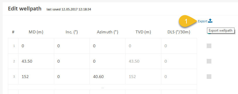
- Find the data you want to export and click Export.
Load data into Excel
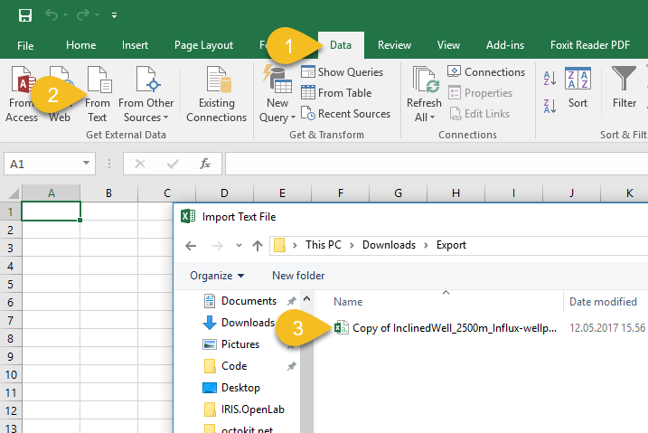
- In the menu, click Data.
- Choose From Text.
- Find and select the file you just exported.
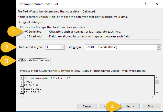
- Make sure Original data type is set to Delimited (default).
- Start import at row should be set to 1 (default) and File origin should be UTF-8.
- Tick the My data has headers checkbox.
- Click Next.
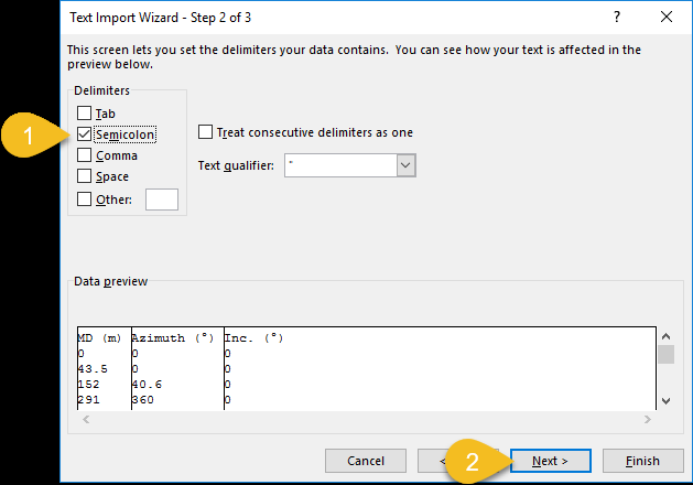
- Make sure Delimiters is set to Semicolon.
- Click Next.
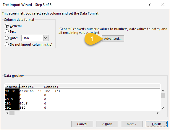
- Click the Advanced... button.
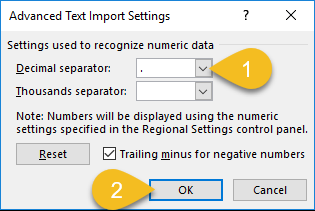
- Make sure Decimal separator is set to . (dot).
- Click OK.
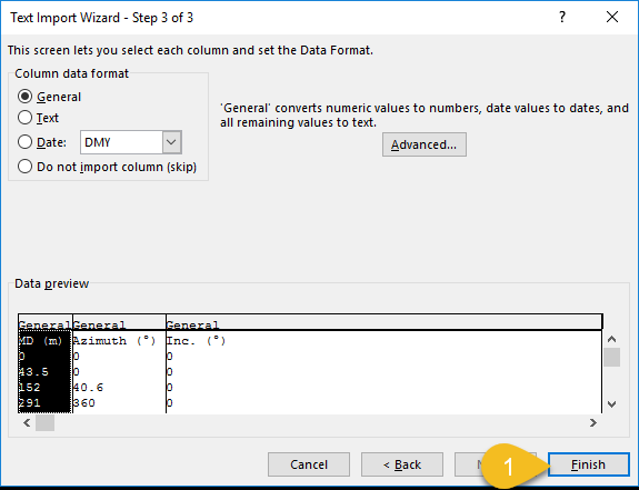
- Click Finish.
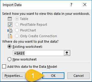
- Click OK to place the data in the selected worksheet.
You should now see the imported data in the worksheet.
Load data into Excel (Alternative)
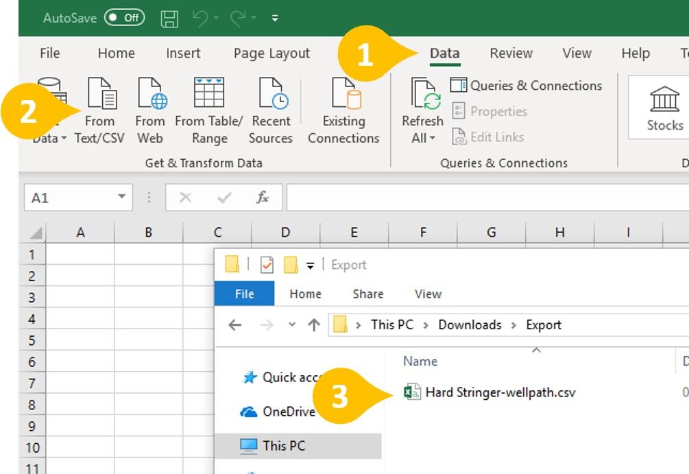
- In the menu, click Data.
- Choose From Text/CSV.
- Find and select the file you just exported.
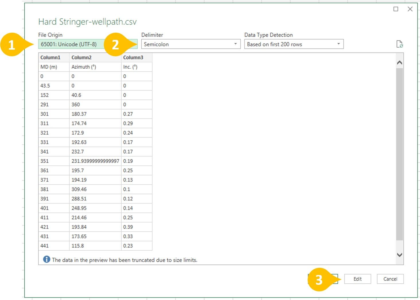
- File origin should be UTF-8
- Delimiter should be Semicolon
- Click Edit
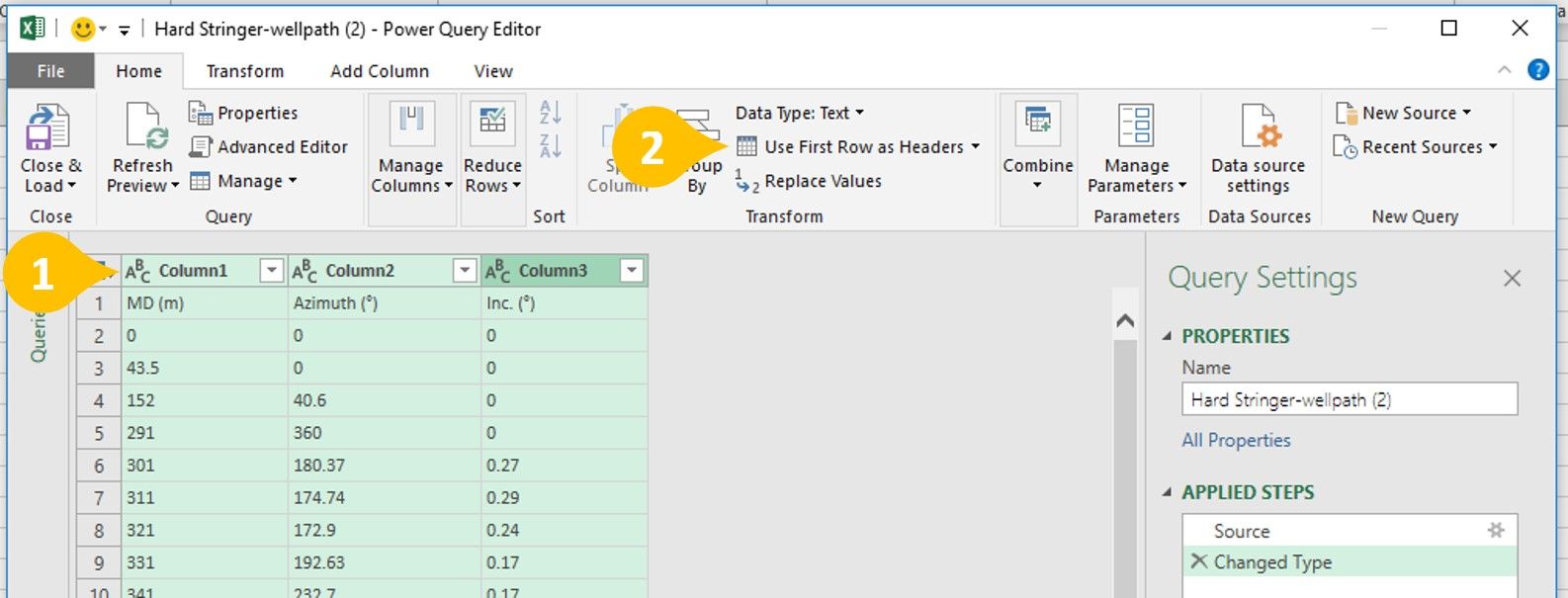
- Select all the columns by clicking each Column Header while holding down the Shift key.
- Select Use First Row as Headers
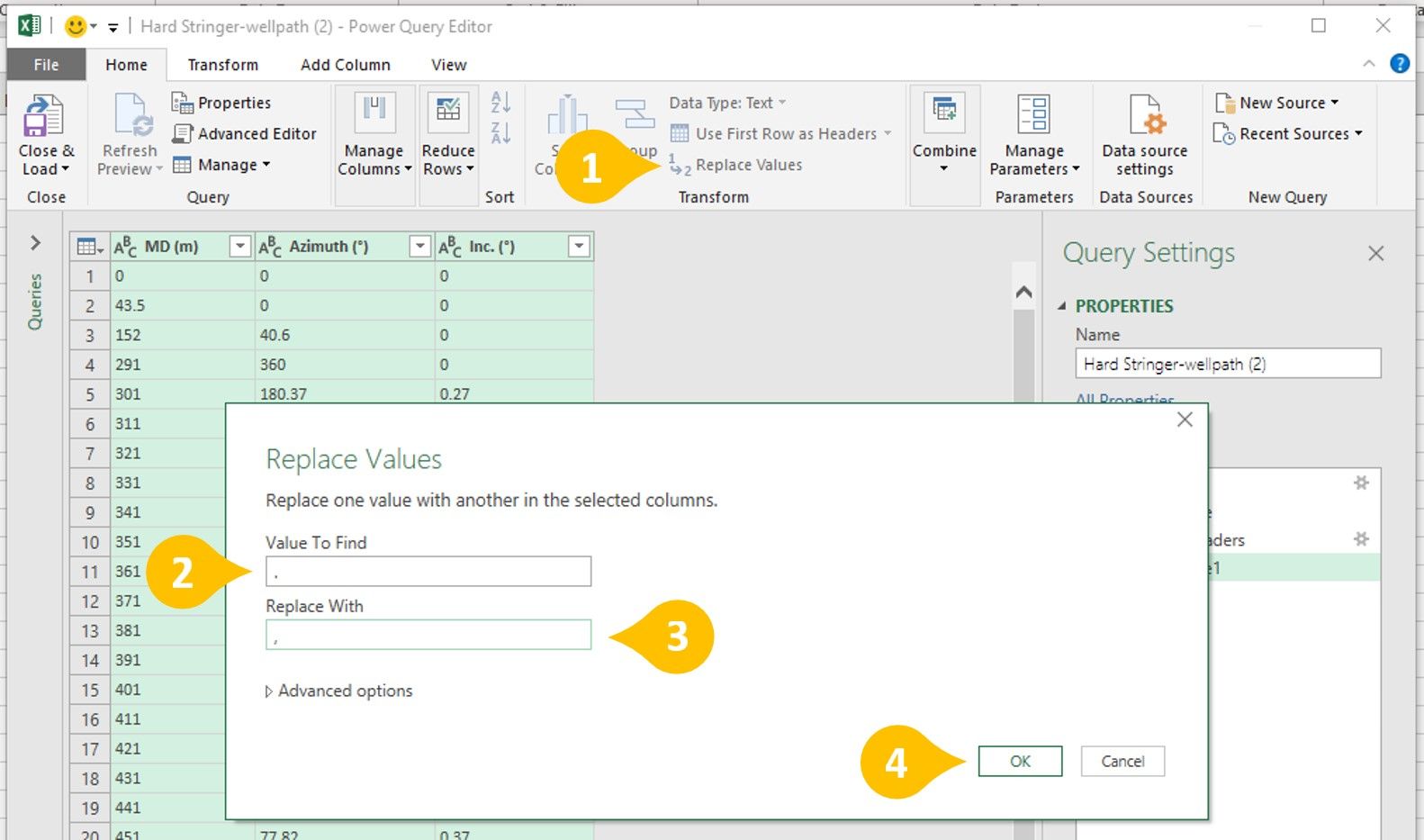
The following are for international users whose Excel uses a decimal seperator other than a decimal point.
- Click Replace Values to open up the Replace Values dialog box.
- Find all decimal points .
- Replace them with your program's decimal separator (in this case a comma ,)
- Click OK
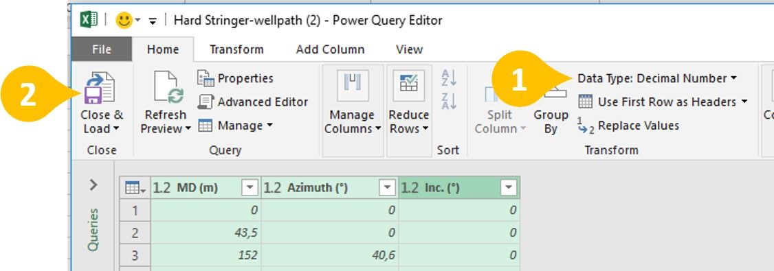
- Change Data Type to Decimal Number
- Finally, click Close & Load
You should now see the imported data in the spreadsheet.
Save data from Excel
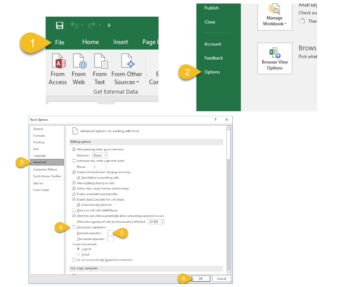
- In the menu, click File.
- Choose Options.
- Go to the Advanced tab.
- Verify that Decimal separator is . (dot). If not, uncheck Use system separators.
- Set Decimal separator to . (dot).
- Click OK.
You're now ready to save the CSV-file.
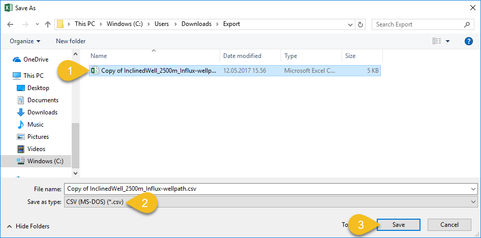
- Mark the file you want to save as.
- Make sure Save as type is set to CSV.
- Click Save.
Importing data back into OpenLab
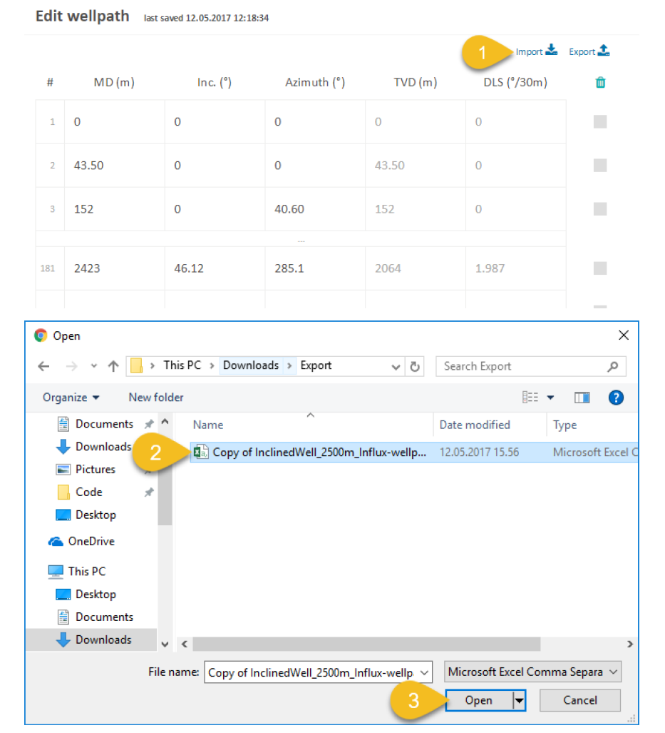
- Navigate to the configuration screen where you want to import your data. Click Import.
- Select the file you saved with Excel.
- Click Open.
You should now see the updated data in the application. If there are errors in the data, you should see the errors highlighted, like this:
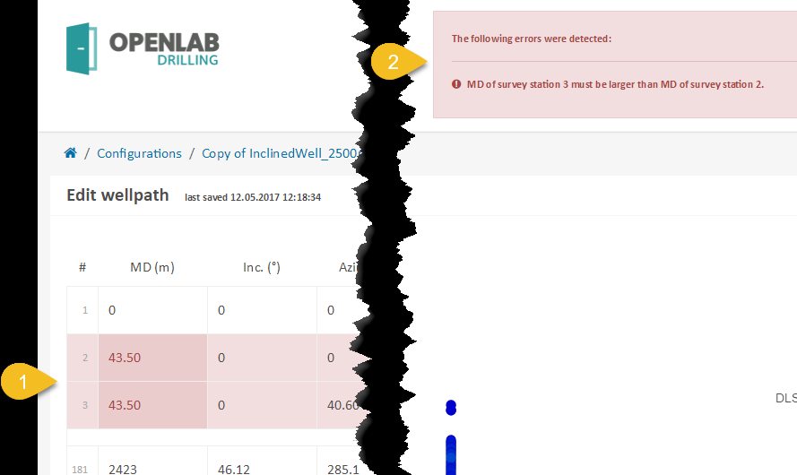
- The data with errors should be highlighted in red.
- In the top-right corner, you should see a description of the errors.
Configuration
Exporting Configuration Data
Most of your well configuration data can be exported as a .csv file. This can be handy if you want to use your data elsewhere. This tutorial walks you through how to accomplish this.
Simulation
Import and Run a Sequence
Currently, OpenLab supports two main type of running a simulation. Interactively or by uploading pre-defined setpoints set for certain times, known in OpenLab as a sequence.
There are two ways to make a sequence: Using our table editor, or importing a .csv file. To create and run a sequence simulation watch this tutorial. To import a sequence watch this tutorial.
Stay tuned to the blog for news about our new sequence simulations!!
Exporting Simulation Data
Exporting simulation data can be done by exporting plot data individually.
If you are having problems with excel or importing/exporting in general, take a look at our thorough guide for help!
And for more efficient ways of accessing your simulation data, stay tuned for the upcoming series on our Python client!
Teams
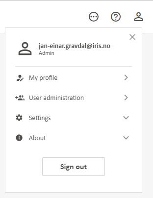
Your username can be associated with multiple teams. If part of multiple teams, your configurations and simulations will be kept separate in the respective users team. To see your current active team and the associated limits, click the user info button in the top right corner of OpenLab and click "My Profile" from the drop-down.
Inviting Someone To A Team
With a paid plan, a team manager can invite several users to a team. To invite a user, click the "User administration" section found in the user settings in the top right corner.
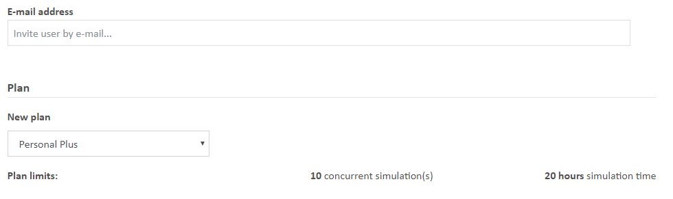
Afterwards, simply click on the "New user" button and decide which plan you want for the user. The main differences between the plans are maximum simulation time and capacity, which will be displayed when selecting the plan.
Removing A Team Member
There are 2 ways a team manager can remove a user(s) from a team. Both of which start by navigating to the "User administration" section found in the user settings in the top right corner.
Option 1) From the "User Administration" section, click on the "Users" tab menu and select the edit user button. Click on the more settings button the right side of the user, and an option to "Remove user from team" will appear. Click this to remove the team member.

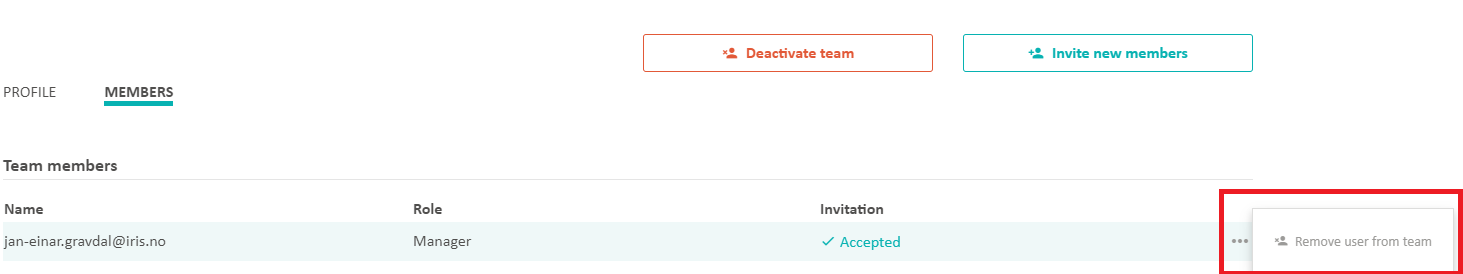
Option 2) Navigate to the team page also found in the "User administration" section. Click on the "Teams" tab and select the "Edit" button of the team you want to remove the user from. Next, click on the "Members" tab and find the user you want to remove. Click on the more settings button on the right side of the user, and an option to "Remove user from team" will appear. Click this to remove the team member.
Switching Teams
If you are part of multiple teams, you switch between them by either clicking the team name in the top-left corner of the home page, or by going to your user settings and clicking "My Profile." This will switch all of configurations and simulations to those associated with the current team, and your simulation capacity and length limits will be changed to reflect your active team settings.
Other Features
Share a Configuration and a Simulation
The configurations and simulations can be shared to anyone with an OpenLab user account. Each configuration has a unique configuration ID, and each simulation has a unique simulation ID. These ID’s can be found in the URL of your browser. It will look something like this:
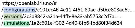
As you can see from the example URL, it contains a configuration ID, as well as a version ID (because there are multiple versions on this configuration), and there is a simulation ID associated with it. By clicking the “Share this page” button on the top right corner in OpenLab, you can copy this link to distribute it. Beware that when you share your configuration with others, the recipient needs to create their own copy to edit and run simulations. If you receive a shared configuration from someone you will see the following message in your OpenLab view:

Change Units
By clicking the more settings button in the top right corner in OpenLab, you can select different unit systems.
MatLab and Python Interfaces
Any user with a user account in OpenLab can also reach the web API through clients other than a web browser. We have currently prepared templates for running the OpenLab Web Enabled Drilling Simulator from Matlab and from Python. These templates can be downloaded from our webpage.
Matlab
Matlab Client: Install, Authenticate, and Run a Simulation
NB: The MatLab client will only communicate with OpenLab if you are using MatLab version 2016b or later.
You must also have a configuration created in the web browser client that you will run the drilling simulation on. For more info on this, check out our tutorials page and click the Configuration button.
Download and Installation
The MatLab OpenLab client can be found in our download section or can be downloaded using this link.
Once you have downloaded the client, simply unzip the contents and open the file GetLoginData.m. This file is where you will put your authentication credentials as described in the following section.
Authentification
Unlike our Python client, the MatLab client requires all 3 user identification parameters. These are as follows:
- API Key
- Username/E-mail
- License ID
To generate these parameters:
1) Go to your User settings in the top right corner of https://live.openlab.app.
2) Select which license you want to generate for (if multiple licenses)
3) Click Generate Matlab login script.
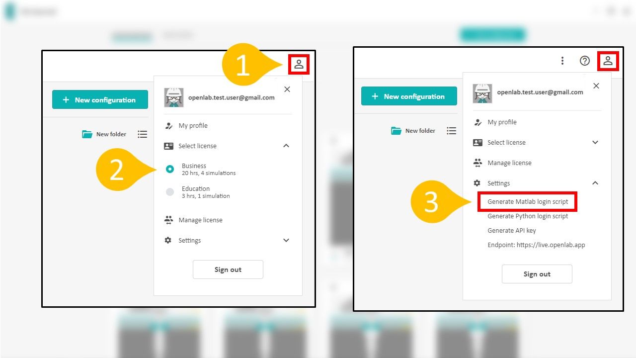
A new API key will be generated, and a form should appear which will overwrite your old API key (if you had one). Copy this key and paste it in the correct place for the upcoming options.
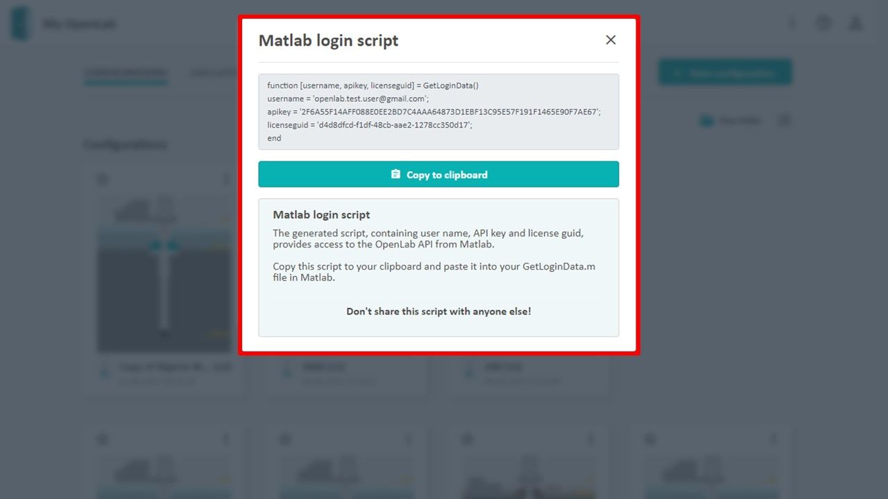
Once you have copied this script, paste it into the GetLoginData.m that was opened in the earlier Download and Installation section.
Run Example Simulation
Open the case file FlowSweep_BHPControl.m and enter the ConfigurationName for which you want to run the simulation on. Again, this must be an existing well configuration that you have created using the OpenLab web client.
Specify a new SimulationName or use the default given. This simulation name can be named anything (duplicates allowed) and will be visible in the browser when you start a simulation from MatLab.
Finally, run the case file FlowSweep_BHPControl.m in MatLab. The simulation will now be visible in the browser under the Simulations tab. You can click the corresponding simulation and view the streamed results as they happen, but you will not be able to give any setpoint inputs.
Python
Simple Drilling Simulation Using Python
Before you start
Make sure your python OpenLab client and credentials are up to date (see our tutorial on how to do this).
Create a new default well configuration in the web client and name it "Offshore Inclined".
Initialize and Authenticate Account
We use the default keyring method which uses our stored credentials (see our tutorial for instructions on this or the other methods if having problems).
import openlab
session = openlab.http_client()
You should see a print out confirming you have been authenticated.
Simulation Initialization
There are several mandatory and optional initialization parameters as listed below (subject to change):
Mandatory:
- Configuration name (must be a pre-existing configuration created in the web client)
- Simulation Name (Whatever you wish to call the simulation)
- Initial Bit Depth (in meters)
Optional:
- Influx Model
- Timestep Interval (Default = 1)
We will only use the 3 mandatory parameters for now:
config_name = "Offshore Inclined"
sim_name = "Drill From Python"
initial_bit_depth = 2500
Now, we can initialize and create the simulation:
sim = session.create_simulation(config_name, sim_name, initial_bit_depth)If you navigate to the web client, you should now see a simulation called "Drill From Python" has been created in the "Simulations" tab, and is awaiting setpoints.
In order to actually drill and advance the wellbore, we initialize with the following 4 setpoints (Make note that all numeric values must be sent in SI units) :
sim.setpoints.RPM = 0 #Hz
sim.setpoints.DesiredROP = 0.02 #m/s
sim.setpoints.TopOfStringVelocity = 0.02
sim.setpoints.FlowRateIn = 2500 / 60000 #60000 is to convert l/min to m^3/s
Advance/Run the Simulation
In order to advance and step the simulation, a setpoint must be sent to the OpenLab server with one mandatory setpoint -> timestep. We do this using a for loop:
simulation_time = 300 # seconds

for i in range(1, simulation_time + 1):
	sim.step(i)
You can watch and verify the simulation is running by clicking on the simulation in the web page.
Ending the Simulation
To end a simulation through the API, a new setpoint must be sent containing the value of ShouldComplete = True. This is done automatically for you in the python client by calling the Simulation class's stop() method:
sim.stop()Note: When running a simulation script (i.e. not interactively in the shell), the default OpenLab session behaviour is to automatically end all initialized simulations. To toggle this feature, you can use the end_simulation_on_exiting flag of the openlab.Simulation class. Or in our case:
sim.end_simulation_on_exiting = True/FalseCreate and Edit a Configuration - Programatically
Specific use case:
- Double all the formation strength UCS
Recommended work flow:
- Create a scratch configuration in the web client to use as a data template to edit.
- Get the configuration data from this scratch configuration via our API. For this case, we will use python alongside the openlab module.
- Programmatically edit/make the desired changes to this configuration data.
- Push the edited data to the API
Walkthrough
For the final code, jump to the bottom section
Create a scratch configuration
Go to https://live.openlab.app/ and login into your account.
Click the "New configuration" button on the homepage and a dialog box should appear. Choose the template that is most closely related to your configuration and name it. You will delete this configuration later.
Take note of the configuration id.
Retrieve configuration data
import openlab

# Auto-generated credentials from https://live.openlab.app
username="hols@norceresearch.no"
apikey=""
licenseguid=""

session = openlab.http_client()
Get the data and print it out to inspect it.
# Copy and paste this id from the web client url endpoint
config_id = ""

data = session.configuration_data(config_id)

print(data)
This outputs an unnavigable chunk of text, so we inspect the dictionaries keys to give us a clue and help navigate to where UCS might be.
print(data.keys())output -> ['Rig', 'Fluids', 'GeoThermal', 'Trajectory', 'DrillString', 'GeoPressure', 'Architecture', 'FormationStrength']
Upon further investigation, we see that FormationStrength is a list of dictionaries, with each dictionary element consisting of a UCS key:value pair.
Let's print out the last element's UCS
# Get the last elements UCS
fs_last = data["FormationStrength"][-1]
ucs_last = fs_last["UCS"]

print(ucs_last)
Edit the data
Now that we have found the data we want to make changes to, we can update it. We will assign the original scratch config data a new value (double the original value).
# Double each UCS
for fs in data["FormationStrength"]:
    fs["UCS"] *= 2
Push the new configuration data
Finally, we create the new configuration by calling the create_configuration(name, data) method, passing in the newly manipulated configuration data.
# Create a new configuration with the edited data
name = "Doubled UCS"
session.create_configuration(name, data)
Now, we have created a new configuration which has double the UCS as the default template. You can verify this by going to the web client and viewing the new configuration.
Final Code
import openlab

# Initialize an openlab session
session = openlab.http_client()

# Get an existing configuration
config_id = "aee5eb03-f550-4c27-81d9-5673cd9b5876"
data = session.configuration_data(config_id)


# Double each UCS
for fs in data["FormationStrength"]:
    fs["UCS"] *= 2

# Create a new configuraition with the edited data
session.create_configuration("New Configuration", data)
Joystick Enablement
You can connect a joystick to your computer and control your setpoints in a browser.
OpenLab currently supports the following joysticks:
- Logitech Extreme 3D Pro
- Logitech Attack 3
Connecting and Enabling Joystick
To connect any of the supported joysticks (see Supported Joysticks section), simply plug it in to any USB port once you are logged in. You should get a joystick connected notification similar to the one below.
The supported joystick is automatically enabled once a simulation has been initialized and manual mode is selected.
Additionally, once a joystick has been enabled, a Joystick button should appear in the interactive sidebar. Clicking this will open your specific joysticks button mapping and controls (see Summary of Joystick Controls section).
If at any time, you wish to stop using the joystick, simply unplug the joystick. You will see a notification like the one below to confirm you have disconnected the joystick.
Summary of Joystick Controls
Calibration
Joystick calibration can be done to reset the 0 value, or neutral resting state, of the joystick's analog axes. To do this, an interactive simulation must be open with the supported joystick plugged in. Once open, click on the joystick “Controls” button located in the sidebar above the setpoints. A pop-up should display the button controls, and at the bottom, a calibration button. Ensure the joystick is in the desired “rest state,” and press the “Calibrate” button. A notification should display confirming calibration was performed.
Dan Sui Associate Professor at UiS
Department of Energy and Petroleum Engineering

Mats Hermansen
SVP Sales, Exebenus


